Showing posts with label alarm. Show all posts

Friday, October 31, 2014

Heat Detector Alarm using UM3561 Circuit Diagram

A very simple heat detector alarm electronic project can be designed using the UM3561 sound generator circuit and some other common electronic parts . This heat detector electronic circuit project uses a complementary pair comprising npn and pnp transistor to detect heat Collector of T1 transistor is connected to the base of the T2 transistor , while the collector of T2 transistor is connected to RL1 relay T3 and T4 transistors connected in darlington configuration are used to amplify the audio signal from the UM3561 ic.

Circuit
When the temperature close to the T1 transistor is hot , the resistance to the emitter –collector goes low and it starts conducting . In same time T2 transistor conducts , because its base is connected to the collector of T1 transistor and the RL1 relay energized and switches on the siren which produce a fire engine alarm sound. This electronic circuit project must be powered from a 6 volts DC power supply , but the UM3561 IC is powered using a 3 volt zener diode , because the alarm sound require a 3 volts dc power supply. The relay used in this project must be a 6 volt / 100 ohms relay and the speaker must have a 8 ohms load and 1 watt power.
Read more

Thursday, October 16, 2014

Build Motorcycle Alarm Circuit Diagram

This is a Motorcycle Alarm Circuit Diagram. Any number of normally open switches may be used. Fit the mercury switches so that they close when the steering is moved or when the bike is lifted off its side-stand or pushed forward off its center-stand. Use micro-switches to protect removable panels and the lids of panniers etc. While at least one switch remains closed, the siren will sound. 

 Motorcycle Alarm Circuit Diagram

Motorcycle


About tw1o minutes after the switches have been opened again, the alarm will reset. How long it takes to switch off depends on the characteristics of the actual components used. But, up to a point, you can adjust the time to suit your requirements by changing the value of C1.The circuit board and switches must be protected from the elements. Dampness or condensation will cause malfunction.Without its terminal blocks, the board is small. Ideally, you should try to find a siren with enough spare space inside to accommodate it. Fit a 1-amp in-line fuse close to the power source. 

This protects the wiring. Instead of using a key-switch you can use a hidden switch; or you could use the normally closed contacts of a small relay. Wire the relay coil so that it is energized while the ignition is on. Then every time you turn the ignition off, the alarm will set itself.When it`s not sounding, the circuit uses virtually no current. This should make it useful in other circumstances. For example, powered by dry batteries and with the relay and siren voltages to suit, it could be fitted inside a computer or any thing else that`s in danger of being picked up and carried away. The low standby current and automatic reset means that for this sort of application an external on/off switch may not be necessary.
Read more

Build a Simple Emergency Light and Alarm Circuit Diagram

This Simple Emergency Light and Alarm Circuit Diagram is permanently plugged into a mains socket andNI-CD batteries are trickle-charged. When a power outage occurs,the lamp automatically illuminates. Instead of illuminating alamp, an alarm sounder can be chosen.When power supply is restored, the lamp or the alarm isswitched-off. A switch provides a “latch-up” function, in orderto extend lamp or alarm operation even when power is restored.Circuit operation:Mains voltage is reduced to about 12V DC at C2`s terminals, bymeans of the reactance of C1 and the diode bridge (D1-D4). Thusavoids the use of a mains transformer.

 Simple Emergency Light and Alarm Circuit Diagram

Simple


Trickle-charging current for the battery B1 is provided by theseries resistor R3, D5 and the green LED D6 that also monitorsthe presence of mains supply and correct battery charging.Q2 & Q3 form a self-latching pair that start operatingwhen a power outage occurs. In this case, Q1 biasing becomespositive, so this transistor turns on the self latching pair.

If SW3 is set as shown in the circuit diagram, the lampilluminates via SW2, which is normally closed; if set the otherway, a square wave audio frequency generator formed by Q4, Q5 andrelated components is activated, driving the loudspeaker.If SW1 is left open, when mains supply is restored the lamp orthe alarm continue to operate. They can be disabled by openingthe main on-off switch SW2.If SW1 is closed, restoration of the mains supply terminateslamp or alarm operation, by applying a positive bias to the Baseof Q2.

Notes:

Close SW2 after the circuit is plugged.Warning! The circuit is connected to 220Vac mains, then some parts in the circuit board are subjected to lethal potential! avoid touching the circuit when plugged and enclose it in a plastic box. 

Parts List
R1____________220K 1/4W Resistor
R2____________470R 1/2W Resistor
R3____________390R 1/4W Resistor
R4______________1K5 1/4W Resistor
R5______________1R 1/4W Resistor
R6_____________10K 1/4W Resistor
R7____________330K 1/4W Resistor
R8____________470R 1/4W Resistor
R9____________100R 1/4W Resistor

C1____________330nF 400V Polyester Capacitor
C2_____________10΅F 63V Electrolytic Capacitor
C3____________100nF 63V Polyester Capacitor
C4_____________10nF 63V Polyester Capacitor

D1-D5________1N4007 1000V 1A Diodes
D6______________LED Green (any shape)
D7___________1N4148 75V 150mA Diode

Q1,Q3,Q4______BC547 45V 100mA NPN Transistors
Q2,Q5_________BC327 45V 800mA PNP Transistors

SW1,SW2________SPST Switches
SW3____________SPDT Switch

LP1____________2.2V or 2.5V 250-300mA Torch Lamp

SPKR___________8 Ohm Loudspeaker

B1_____________2.5V Battery (tw1o AA NI-CD rechargeable cells wired in series)

PL1____________Male Mains plug

Read more

Thursday, October 9, 2014

5 Zone Alarm Circuit diagram and explanation

Each zone alarm uses a normally closed contact. These can be micro switches or standard alarm contacts (usually reed switches). Zone 1 is a timed zone which must be used as the entry and exit point of the building. Zones 2 - 5 are immediate zones, which will trigger the alarm with no delay. Some RF immunity is provided for long wiring runs by the input capacitors, C1-C5. C7 and R14 also form a transient suppresser. The key switch acts as the Set/Unset and Reset switch.


For good security this should be the metal type with a key. At switch on, C6 will charge via R11, this acts as the exit delay and is set to around 30 seconds. This can be altered by varying either C6 or R11. Once the timing period has elapsed, LED6 will light, meaning the system is armed. LED6 may be mounted externally (at the bell box for example) and provides visual indication that the system has set. Once set any contact that opens will trigger the alarm, including Zone 1.

To prevent triggering the alarm on entry to the building, the concealed re-entry switch must be operated. This will discharge C6 and start the entry timer. The re-entry switch could be a concealed reed switch, located anywhere in a door frame, but invisible to the eye. The panic switch, when pressed, will trigger the alarm when set. Relay contacts RLA1 provide the latch, RLA2 operate the siren or buzzer.
Read more

Wednesday, September 24, 2014

Fire Alarm Circuit Diagram

The Fire Alarm circuit presented here is very simple, a diode reverse-biased germanium is used as a heat sensor low cost. In this project you can use two or three diodes connected in parallel at different locations in case of fire any of the diodes can activate the alarm. 

The germanium diode at normal room temperature, its resistance inverse diode is very high, in the order of more than 10K ohms no effect on transistor Q1 conducts and maintains to the reset pin 4 of the IC 555 in its ground level , and so the alarm is not activated. 

Fire Alarm Circuit Diagram

Fire Alarm Circuit Diagram
 

When the temperature in the vicinity of diode (sensor) increases, in case of fire (about 70 degrees) reverse resistance of diode germanium falls below a value of 1K ohms, Q1 driving IC 555 and pin 4 becomes positive through the resistor R1, which activates the alarm.


Read more

Wire Break Alarm With Delay Circuits Diagram

Simple Wire-Break Alarm With Delay  Alarm and Security Here is a simple circuit of wire-break alarm that activates after a delay of 15 to 30 seconds. When the thin-wire loop running across the entrance door is broken, the alarm sounds after a delay of 15 to 30 seconds, the time period set through VR1. Thus the occupants get sufficient time to lock the room from the outside and catch the thief. 

 The circuit uses CD4060, which is a 14-stage ripple-carry binary counter/divider and oscillator. It is wired as a timer here and does not need input pulse for trigger. CD4060 gets activated as soon as the power supply is switched on. Output O13 of CD4060 goes high after the lapse of preset delay set through VR1. Transistor SL100 (T2) is wired as a switch to power the timer section built around CD4060. When the wire loop is closed, transistor T2 does not conduct. So power to the timer circuit is not available and the piezobuzzer does not sound. 

Wire-Break Alarm With Delay Circuit Schematic

Wire-Break Alarm With Delay Circuit Schematic

On the other hand, when the wire loop is broken by some intruder, transistor T2 conducts to power the circuit and the piezobuzzer sounds after 15 to 30 seconds. IC1 can be reset by connecting the wire loop or interrupting the supply. The circuit works off regulated 9V-12V. Assemble it on a general-purpose PCB and enclose in a metallic or plastic box of appropriate size. Connect piezobuzzer PZ1 through external wires and complete the installation. Link
Read more

Tuesday, September 23, 2014

Make Relay Based Motorcycle Alarm Circuit Diagrams

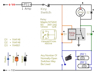
You can Make Relay Based Motorcycle Alarm Circuit Diagrams. You can use them to protect your motorcycle - but they have many more applications. If you use relays with 6-volt coils - theyll protect your "Classic Bike". Both alarms are very small. The completed boards occupy about half a cubic-inch - 8 cc. The standby current is zero - so they wont drain your battery.

Relay Based Motorcycle Alarm Circuit Diagram 1 uses a SPCO/SPDT relay - but you really only need to use a SPST relay. If you are going to use the veroboard layout provided - youll need to use the style of relay specified. But you can build the alarm using whatever style of relay you have available.

Relay Based Motorcycle Alarm Circuit Diagram 1

Make Relay Based Motorcycle Alarm Circuit Diagrams


Any number of normally-open switches may be used. Fit the mercury switches so that they close when the steering is moved or when the bike is lifted off its side-stand or pushed forward off its centre-stand. Use micro-switches to protect removable panels and the lids of panniers etc. When one of the trigger-switches is closed - the relay will energize and the siren will sound.

You can choose what happens next. If you build the circuit as shown, the siren will continue to sound until you turn it off - or until the battery is exhausted. But, if you leave out D3 - the siren will stop sounding immediately the trigger-switch is re-opened.

While youre within earshot of your machine - the former configuration is best. You can always turn off the alarm yourself. But if you are going to be away from your bike for any length of time - and you dont want to cause a nuisance - then the latter configuration is probably more suitable. If you include a SPST switch in series with D3 - you can select the behaviour that best suits the circumstances at any given time.

Relay Based Motorcycle Alarm Circuit Diagram 1a

Relay Based Motorcycle Alarm Circuit Diagram 1a


Relay coils and some sounders produce high reverse-voltage spikes that will destroy sensitive electronic components. D1 and D2 are there to short-circuit these spikes before they can do any damage. Although there is nothing in the alarm circuit itself that could be damaged - I have no idea what other electronic equipment might be connected to the same power supply. So I included the two diodes as a precaution. If youre satisfied that theres nothing on your bike that might be damaged in this way - you can leave out the two diodes.

Relay Based Motorcycle Alarm Circuit Diagram 2 uses a DPCO/DPDT relay - but you really only need to use a DPST relay. If you are going to use the veroboard layout provided - youll need to use the style of relay specified. But you can build the alarm using whatever style of relay you have available.

Relay Based Motorcycle Alarm Circuit Diagram 2

Relay Based Motorcycle Alarm Circuit Diagram
 Any number of normally-open switches may be used. Fit the mercury switches so that they close when the steering is moved or when the bike is lifted off its side-stand or pushed forward off its centre-stand. Use micro-switches to protect removable panels and the lids of panniers etc. When one of the trigger-switches is closed - the relay will energize and the siren will sound.


You can choose what happens next. If you build the circuit as shown, the siren will continue to sound until you turn it off - or until the battery is exhausted. But, if you leave out the (yellow) solder-bridge in the top left-hand corner of the diagram - the siren will stop sounding immediately the trigger-switch is re-opened.

While youre within earshot of your machine - the former configuration is best. You can always turn off the alarm yourself. But if you are going to be away from your bike for any length of time - and you dont want to cause a nuisance - then the latter configuration is probably more suitable. Connect a SPST switch in place of the (yellow) solder-bridge - and you can select the behaviour that best suits the circumstances at any given time.

Relay Based Motorcycle Alarm Circuit Diagram 2 a
Relay Based Motorcycle Alarm Circuit Diagram 2

 Relay coils and some sounders produce high reverse-voltage spikes that will destroy sensitive electronic components. D1 and D2 are there to short-circuit these spikes before they can do any damage. Although there is nothing in the alarm circuit itself that could be damaged - I have no idea what other electronic equipment might be connected to the same power supply. So I included the two diodes as a precaution. If youre satisfied that theres nothing on your bike that might be damaged in this way - you can leave out the two diodes.

Whichever alarm you build - the circuit board and switches must be protected from the elements. Dampness or condensation will cause damage. Without the terminal blocks - the board is small. Ideally, you should try to find a siren with enough spare space inside to accommodate it. Fit a 1-amp in-line fuse as close as possible to the power source. This is Very Important. The fuse is there to protect the wiring - not the circuit board. Instead of using a key-switch you can use a hidden switch; or you could use the normally-closed contacts of a small relay. Wire the relay coil so that its energized while the ignition is on. Then every time you turn the ignition off - the alarm will set itself.

When the alarms are not sounding - the circuits use no current. This should make them useful in other circumstances - where a power supply is not readily available. Powered by dry batteries - with the relay and siren voltages chosen to suit - the alarms could be fitted almost anywhere. 

Sourced By : Streampowers

Read more

Friday, September 19, 2014

Simple Multidoor Opening Alarm with Indicator

This door-opening alarm alerts you of intruders. You can use it for up to three doors. You simply need to fit a small unit including reed switch on each doorframe and fix a magnet on the moving door such that the magnet aligns with the reed switch when the door is closed. A separate unit incorporating the power supply, three LEDs and a buzzer is to be kept by your side inside your room. A three-core ribbon cable from this unit goes to each door unit. One core goes to the positive terminal, second to the negative terminal and third to the output of the unit. When the door is closed, the reed switch terminals are shorted and the alarm does not sound.

 Multidoor Opening Alarm with Indicator Circuit Diagram

 Multidoor Opening Alarm with Indicator Circuit Diagram

When door 1 is opened by someone, transistors in the corresponding door unit conduct and the buzzer sounds. LED1 glows to indicate opening of door 1. Due to diode latching action, the alarm will sound continuously even after the door is closed. It can be stopped only by pressing the reset switch of the door unit.

Regulated 9V to 12V DC for operating the circuit is derived from AC mains and fed to the three units mounted on the doors. Battery-backup is also provided. When all the three doors are simultaneously opened, all the three LEDs will glow.

This arrangement can be extended for more doors by increasing the number of door units connected to the audio-visual indication unit.


Author Pardeep G
Read more

Simple Mock Alarm with Call Bell Circuit Diagram

Simple Mock Alarm with Call Bell Circuit Diagram is a fully automatic mock alarm to ward off any intruder to your house. The alarm becomes active at sunset and remains ‘on’ till morning. The flashing light-emitting diodes (LEDs) and beeps from the unit simulate the functioning of a sophisticated alarm system. Besides, the circuit turns on and off a lamp regularly at an interval of 30 minutes throughout the night. It also has a call bell facility.

The circuit is built around CMOS IC CD4060B (IC1), which has an internal oscillator and a 14-stage binary divider to provide a long delay without using a high-value resistor and capacitor.

Press switch S2 to provide 9V power supply to the circuit. During daytime, light-dependent resistor LDR1 offers little resistance and transistor T1 conducts. This drives transistor T2 into the cut-off mode, as its base is pulled to ground via transistor T1. Reset pin 12 of IC1 remains high as long as transistor T2 is cut off. This keeps the oscillator of IC1 (comprising resistors R5 and R6 and capacitor C1) disabled and its outputs remain low. The sensitivity of LDR1 can be adjusted using preset VR1.

 Simple Mock Alarm with Call Bell Circuit Diagram


Simple Mock Alarm with Call Bell Circuit Diagram


When the sunlight decreases in the evening, the resistance of LDR1 increases to cut off transistor T1. This drives transistor T2 into conduction mode and its collector voltage goes low. At the same time, reset pin 12 of IC1 goes low to enable the oscillator of IC1 and the oscillator starts oscillating. The O3 output (pin 7) of IC1 goes high every five seconds to light up the LEDs (LED1 and LED2) and activate the buzzer. Resistor R8 limits the tone produced from the buzzer.

At the same time, O13 output of IC1 (pin 3) goes high every 30 minutes to forward bias transistor T3 to energise relay RL1 and lamp L1 connected to the normally opened (N/O) contacts of relay RL1 glows. This cycle repeats till morning.

The call bell is built around IC 4822 (IC2). Its inbuilt musical tone generator generates different tones at each trigger. The frequency of the tone can be controlled through external components R11 and C2. The output at pin 11 of IC2 is amplified by transistor T4.

When push-to-on switch S1 is pressed once, trigger pin 4 of IC2 gets a positive trigger from the positive rail (reduced by zener diode to 3.3V) via resistor R10 and IC2 starts producing a melody. Resistor R10 limits the current to the trigger pin of IC2 and resistor R12 prevents any false triggering. Zener diode ZD1 provides the 3.3V required for IC 4822.

The circuit works off 9V regulated power supply. Assemble the circuit on any general-purpose PCB and enclose it in a waterproof plastic box with holes for mounting LEDs on the rear and the LDR on the top of the box. Place the LDR such that sunlight falls on it directly. Mount the unit on the pillar of the entrance gate. To avoid unnecessary illumination of the LDR, install lamp L1 away from the unit in the porch of the house. Keep the speaker inside the room.


Aothur D. Mohan Kumar and Thanx Streampowers
Read more