Showing posts with label build. Show all posts

Thursday, October 16, 2014

Build Motorcycle Alarm Circuit Diagram

This is a Motorcycle Alarm Circuit Diagram. Any number of normally open switches may be used. Fit the mercury switches so that they close when the steering is moved or when the bike is lifted off its side-stand or pushed forward off its center-stand. Use micro-switches to protect removable panels and the lids of panniers etc. While at least one switch remains closed, the siren will sound. 

 Motorcycle Alarm Circuit Diagram

Motorcycle


About tw1o minutes after the switches have been opened again, the alarm will reset. How long it takes to switch off depends on the characteristics of the actual components used. But, up to a point, you can adjust the time to suit your requirements by changing the value of C1.The circuit board and switches must be protected from the elements. Dampness or condensation will cause malfunction.Without its terminal blocks, the board is small. Ideally, you should try to find a siren with enough spare space inside to accommodate it. Fit a 1-amp in-line fuse close to the power source. 

This protects the wiring. Instead of using a key-switch you can use a hidden switch; or you could use the normally closed contacts of a small relay. Wire the relay coil so that it is energized while the ignition is on. Then every time you turn the ignition off, the alarm will set itself.When it`s not sounding, the circuit uses virtually no current. This should make it useful in other circumstances. For example, powered by dry batteries and with the relay and siren voltages to suit, it could be fitted inside a computer or any thing else that`s in danger of being picked up and carried away. The low standby current and automatic reset means that for this sort of application an external on/off switch may not be necessary.
Read more

Build a Simple Emergency Light and Alarm Circuit Diagram

This Simple Emergency Light and Alarm Circuit Diagram is permanently plugged into a mains socket andNI-CD batteries are trickle-charged. When a power outage occurs,the lamp automatically illuminates. Instead of illuminating alamp, an alarm sounder can be chosen.When power supply is restored, the lamp or the alarm isswitched-off. A switch provides a “latch-up” function, in orderto extend lamp or alarm operation even when power is restored.Circuit operation:Mains voltage is reduced to about 12V DC at C2`s terminals, bymeans of the reactance of C1 and the diode bridge (D1-D4). Thusavoids the use of a mains transformer.

 Simple Emergency Light and Alarm Circuit Diagram

Simple


Trickle-charging current for the battery B1 is provided by theseries resistor R3, D5 and the green LED D6 that also monitorsthe presence of mains supply and correct battery charging.Q2 & Q3 form a self-latching pair that start operatingwhen a power outage occurs. In this case, Q1 biasing becomespositive, so this transistor turns on the self latching pair.

If SW3 is set as shown in the circuit diagram, the lampilluminates via SW2, which is normally closed; if set the otherway, a square wave audio frequency generator formed by Q4, Q5 andrelated components is activated, driving the loudspeaker.If SW1 is left open, when mains supply is restored the lamp orthe alarm continue to operate. They can be disabled by openingthe main on-off switch SW2.If SW1 is closed, restoration of the mains supply terminateslamp or alarm operation, by applying a positive bias to the Baseof Q2.

Notes:

Close SW2 after the circuit is plugged.Warning! The circuit is connected to 220Vac mains, then some parts in the circuit board are subjected to lethal potential! avoid touching the circuit when plugged and enclose it in a plastic box. 

Parts List
R1____________220K 1/4W Resistor
R2____________470R 1/2W Resistor
R3____________390R 1/4W Resistor
R4______________1K5 1/4W Resistor
R5______________1R 1/4W Resistor
R6_____________10K 1/4W Resistor
R7____________330K 1/4W Resistor
R8____________470R 1/4W Resistor
R9____________100R 1/4W Resistor

C1____________330nF 400V Polyester Capacitor
C2_____________10΅F 63V Electrolytic Capacitor
C3____________100nF 63V Polyester Capacitor
C4_____________10nF 63V Polyester Capacitor

D1-D5________1N4007 1000V 1A Diodes
D6______________LED Green (any shape)
D7___________1N4148 75V 150mA Diode

Q1,Q3,Q4______BC547 45V 100mA NPN Transistors
Q2,Q5_________BC327 45V 800mA PNP Transistors

SW1,SW2________SPST Switches
SW3____________SPDT Switch

LP1____________2.2V or 2.5V 250-300mA Torch Lamp

SPKR___________8 Ohm Loudspeaker

B1_____________2.5V Battery (tw1o AA NI-CD rechargeable cells wired in series)

PL1____________Male Mains plug

Read more

Tuesday, September 23, 2014

Build a 16 LED Chaser Circuit Diagram

This 16 LED Chaser Circuit Diagram is a double direction flash. Similar to Digital Ping- Pong 1, there is a movement of a lit dot, up and down along the LEDs length.

16 LED Chaser Circuit Diagram

16 LED Chaser Circuit Diagram


When the D16 lit the situation changes and there is a reverse movement. Lit D15-14 ……D16, is lit making circles when the circuit is under power. The IC1 is an unstable flip- flop supplying with stable frequency pulses (the frequency can be changed by TR1, adjusting the velocity of the LEDs up and down).

This frequency supplies the IC3 (which is a 4-Bit UP and DOWN counter) through 2 gates A-B of the IC2. The output counter supplies the IC4 that is the driver of the LEDs. The parts C- D of The IC2, make a R-S flip- flop, that changes situation, when the edge LEDs D1 and D16 lit.

We have an electronic limit for the situation change. In proportion the shape we make with the LEDs, we can have the proportionate optional result, making various effects.

Part List

R1= 100Kohms
R2= 220Kohms
R3= 470 ohms
TR1= 1Mohms
C1= 330nF 100V MKT
D1-16= LED 5mm
IC1= 555
IC2= 7400
IC3= 74193
IC4= 74154
Read more

Build A Homemade Fence Charger Energizer Circuit Explained

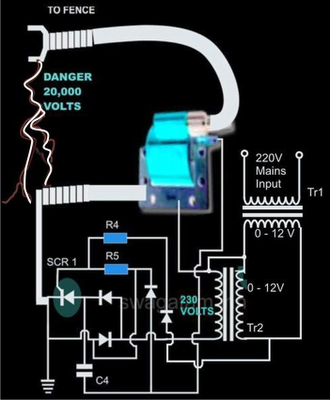
The electric fence charger circuit presented here is basically a high voltage pulse generator. The super high voltage is derived from a commonly used automobile ignition coil. An a stable multivibrator is used to generate the required frequency to drive the ignition coil. Another a stable is used to control the pulses supplied to the fence.

 If you have large agricultural fields and desperately need to protect the crops from uninvited guests like animals and possibly humans, then this electric fence charger device is just what you are looking for. Build and install it yourself. An electric fence is an electrified high voltage barrier which produces painful shocks if physically touched or manipulated. Thus such fencing basically function as deterrents for animals as well as human intruders and stop them from crossing the restricted boundary.

Build  A Homemade Fence Charger Energizer Circuit Explained

Build  A Homemade Fence Charger Energizer Circuit Explained


The present circuit of an electric fence charger is designed and tested by me and has proved sufficiently powerful for the application. The circuit is able to produce voltage pulses up to 20,000 volts, needless to say about the fatality rate involved with it. However the pulses being intermittent, provides the subject with enough time to realize, recover and eject.

The generated pulse is so powerful that it can easily arc and fly-off between short distances of around a cm. so the fencing conductor needs to be separated adequately to avoid leakages through arcing and sparking. If not tackled, may drastically reduce the effectiveness of the unit.

Here the generation of high voltage is primarily carried out by an automobile ignition coil.

The winding ratios of an ignition coil are specifically designed and intended for creating high voltage arc between a two closely spaced conductors inside the ignition chamber to initiate the ignition process in vehicles.

Basically it’s just a step-up transformer, which is able to step-up an input applied voltage at its primary winding to monstrous levels at its output or the secondary winding.

SOME POINTS OF THE CIRCUIT AND THE IGNITION COIL IS VERY DANGEROUS TO TOUCH WHEN POWERED. ESPECIALLY THE IGNITION COIL OUTPUT IS TOO LETHAL AND MAY EVEN CAUSE PARALYSIS.

Let’s diagnose the whole thing more deeply.

Circuit Description


In the CIRCUIT DIAGRAMwe see that the entire circuit is basically comprised of four stages.

A DC oscillator stage, An intermediate 12 to 230 volts step-up stage, The voltage collector and firing stage and The super high voltage-booster stage.

 TR1 and TR2 are two normal step-down transformers whose secondary windings are connected through SCR2. TR2’s input primary winding may be selected as per the country specification.

However, TR1’s primary should be rated at 230 volts.

IC1 along with the associated components forms a normal astable multivibrator stage. The supply voltage to the circuit is derived from the secondary of TR2 itself.

The output from the astable is used to trigger SCR2 and the whole system, at a particular fixed intermittent rate as per the settings of P1.

During the ON periods, SCR2 connects the 12 volt AC from TR2 to the secondary of TR1 so that a 230 volt potential instantly becomes available at the other end of TR1.

 This voltage is fed to the voltage-firing stage consisting of the SCR1 as the main active component along with a few diodes, resistor and the capacitor C4.

The fired voltage from SCR1 is dumped into the primary winding of the ignition coil, where it is instantly pulled to a massive 20,000 volts at its secondary winding. This voltage may be suitably terminated into the fencing.

The high voltage generated by this electric fence charger will need to be carefully applied across the whole length of the fence.

The two poles from the ignition coil connected to the fence wiring should be kept at least 2 inches apart.

 The pillars of the fence should be ideally made of plastic or similar non conducting material, never use metal and not even wood (wood tend to absorb moisture and may give path to leakages).

 Parts List

R4 = 1K, 1WATT,
R5 = 100 OHMS, 1WATT,
P1 = 27K PRESET
C4 = 105/400V PPC,
ALL DIODES ARE 1N4007,
IC = 555
TR1 = 0-12V/3Amp (120 or 230V)
TR2 = 0-12V/1Amp (120 or 230V)
BOTH THE SCRs ARE C106 OR PREFERABLY BT151,

TWO WHEELER IGNITION COIL IS SHOWN IN FLUORESCENT BLUE COLOR

Read more

Build a Flashing Light with Twilight Switch Circuit Diagram

Build a Flashing Light with Twilight Switch Circuit Diagram. Flashing light is very useful in order to indicate any obstruction or working in progress. The project automatic flashing light with twilight switch flash light in dark but during day it automatically turns off itself.

The circuit diagram of automatic flashing light with twilight switch is shown below where LDR is used as sensor. In the presence of light LDR offer low resistance and in dark it offers high resistance. When there is absence light, LDR offer high resistances which turn off the transistor T1. Due to this darlington pair made from transistor T2 and T3 is turn on which further glow bulb. The feedback from its output is given to the junction of resistor R2 and LDR as shown in circuit diagram. Due to feedback this circuit works as oscillator which work as flasher. Variable resistor VR1 is used to adjust the sensitivity of LDR.

Flashing Light with Twilight Switch Circuit Diagram
 
Flashing Light with Twilight Switch Circuit Diagram


PARTS LIST
Resistors (all ¼-watt, ± 5% Carbon unless stated otherwise)
R1 = 2.2 KΩ
R2, R3 = 1 KΩ
R4 = 3.3 KΩ
VR1 = 25 KΩ
Capacitors
C1 = 1 µF – 10 µF
Semiconductors
T1, T2 = BC547B
T3 = BEL187-P
Miscellaneous
LDR
B1 = 3V to 10V bulb
Read more

Build Your Own RC Tankbot

Here’s a blog post that will show you the setup you’ll need to make your own do-it-yourself radio controlled (RC) tankbot from the ground up. This example uses a few kits from Solarbotics to build your own RC controller, communication link, and tankbot using minimal parts. We even managed to get 250 feet of range out of the deal!

How to Build Your Own RC Tankbot


For this exploit we invite you to move over to the dark side, as the heart of the project isn’t Xbees but instead 2.4GHz IEEE 802.15.4 Radio Frequency Network modules from Synapse Wireless which are actually super simple to use and configure. This post will merely get you started with building a general RC platform, feel free to modify/hack the system to suite your own diabolical requirements. [Link]
Read more

Build a Simple Digital Electronic Lock Circuit Diagram

Build a Simple Digital Electronic Lock Circuit Diagram. This is a Build a Simple Digital Electronic Lock Circuit Diagram. The digital lock shown below uses 4 common logic ICs to allow controlling a relay by entering a 4 digit number on a keypad. The first 4 outputs from the CD4017 decade counter (pins 3,2,4,7) are gated together with 4 digits from a keypad so that as the keys are depressed in the correct order, the counter will advance.

Simple Digital Electronic Lock Circuit Diagram

Simple Digital Electronic Lock Circuit Diagram


As each correct key is pressed, a low level appears at the output of the dual NAND gate producing a high level at the output of the 8 input NAND at pin 13. The momentary high level from pin 13 activates a one shot circuit which applies an approximate 80 millisecond positive going pulse to the clock line (pin 14) of the decade counter which advances it one count on the rising edge.

A second monostable, one shot circuit is used to generate an approximate 40 millisecond positive going pulse which is applied to the common point of the keypad so that the appropriate NAND gate will see two logic high levels when the correct key is pressed (one from the counter and the other from the key). The inverted clock pulse (negative going) at pin 12 of the 74C14 and the positive going keypad pulse at pin 6 are gated together using two diodes as an AND gate (shown in lower right corner). The output at the junction of the diodes will be positive in the event a wrong key is pressed and will reset the counter.

When a correct key is pressed, outputs will be present from both monostable circuits (clock and keypad) causing the reset line to remain low and allowing the counter to advance. However, since the keypad pulse begins slightly before the clock, a 0.1uF capacitor is connected to the reset line to delay the reset until the inverted clock arrives. The values are not critical and various other timing schemes could be used but the clock signal should be slightly longer than the keypad pulse so that the clock signal can mask out the keypad and avoid resetting the counter in the event the clock pulse ends before the keypad pulse.

The fifth output of the counter is on pin 10, so that after four correct key entries have been made, pin 10 will move to a high level and can be used to activate a relay, illuminate an LED, ect. At this point, the lock can be reset simply by pressing any key.

The circuit can be extended with additional gates (one more CD4011) to accept up to a 8 digit code. The 4017 counting order is 3 2 4 7 10 1 5 6 9 11 so that the first 8 outputs are connected to the NAND gates and pin 9 would be used to drive the relay or light. The 4 additional NAND gate outputs would connect to the 4 remaining inputs of the CD4068 (pins 9,10,11,12). The circuit will operate from 3 to 12 volts on 4000 series CMOS but only 6 volts or less if 74HC parts are used. The circuit draws very little current (about 165 microamps) so it could be powered for several months on 4 AA batteries assuming only intermittent use of the relay.

Sourced By : Streampowers
Read more

Friday, September 19, 2014

Build a 10W 225 400mhz Linear Amplifier Circuit Diagram

Build a 10w 225-400mhz Linear Amplifier Circuit Diagram. This circuit broadband amplifier covers the 225-400 MHz military communications band producing 10 watt RF output power and operating from a 28 volt supply. The amplifier can be used as a driver for higher power devices such as 2N6439 and MRF327. The circuit is designed to be driven by a 50 ohm source and operate into a nominal 50 ohm load. 

 10W 225-400mhz Linear Amplifier Circuit Diagram


 10W 225-400mhz Linear Amplifier Circuit Diagram

The input matching network consists of a section composed of C3, C4, Z2, C5 and C6. C2 is a dc blocking capacitor, and Tl is a 4:1 impedance ratio coaxial transformer. Z1 is a 50 ohm transmission line. A compensation network consisting of Rl, Cl, and LI is used to improve the input VSWR and flatten the gain response of the amplifier. 

L2 and a small ferrite bead make up the base bias choke. The output network is made up of a microstrip L-section consisting of Z3 and C7, and a high pass section consisting of C8 and L3. C8 also serves as a dc blocking capacitor. Collector decoupling is accomplished through the use of L4, L5, C9, C10, Cll, C12, and C13.
Read more

Build a Rechargeable Torch Based on White LED

Rechargeable torches don’t come without problems. You need to replace the bulbs and charge the batteries frequently. The average incandescent light-emitting diode (LED) based torch, for instance, consumes around 2 watts. Here’s a rechargeable white LED-based torch that consumes just 300 mW and has 60 per cent longer service life than an average incandescent torch.

 Rechargeable Torch Based on White LED Circuit Diagram


 Rechargeable Torch Based on White LED Circuit Diagram

Fig. 1 shows the circuit of the rechargeable white LED-based torch. The reactive impedance of capacitors C1 through C3 (rated for 250V AC) limits the current to the charger circuit. The resistor across the capacitors provides a discharge path for the capacitors after the battery is charged. The red LED1 indicates that the circuit is active for charging.

The torch uses three NiMH rechargeable button cells, each of 1.2V, 225 mAH. A normal recharge will take at least 12 hours. Each full recharge will give a continuous operational time of approximately 2.5 hours. Recharge the battery to full capacity immediately after use to ensure its reliability and durability. The charging current is around 25 mA.

Build a Rechargeable Torch Based on White LED

A voltage booster circuit is required for powering the white LEDs (LED2 through LED4). An inverter circuit is used to achieve voltage boosting. Winding details of the inverter transformer using an insulated ferrite toroidal core is given in the schematic. The number of 35 SWG wire turns in the primary and secondary coils (NP and NS) are 30 and 3, respectively. If the inverter does not oscillate, swap the polarity of either (but not both) the primary or the secondary winding. A reference voltage from resistor R5 provides a reflected biasing to the transistor, and keeps the output constant and regulated. The suggested enclosure for the torch is shown in Fig. 2.


Author: T.A . Babu
Read more