Showing posts with label led. Show all posts

Tuesday, November 4, 2014

Regulated 24 Watt Broad Spectrum LED

This project involves constructing an energy efficient broad spectrum LED lamp system. The lamp is useful for indoor reflective room lighting. It has a broad color spectrum that more closely approximates the light of the sun when compared to fluorescent bulbs and white-only LEDs. The light level is regulated and the light that is produced does not flicker.

The six differently colored LED stars, made by LedEngin, Inc., are rated at 5 watts (nominal). The LED array and associated current regulator consume 1 amp at 24VDC (24 Watts). NEVER stare directly at this lamp when it is running at full operating power, it is DANGEROUSLY BRIGHT.

Regulated 24 Watt Broad Spectrum LED Circuit diagram : 

24


With the LEDs shown, the combined color of the lamp has a pinkish white hue. The 5 Watt ratings of the LEDs are not precise, the white, blue and green LEDs consume about 4W and the lower voltage red, orange and deep red LEDs consume about 3W. The current regulator keeps the LED brightness constant and insures that the LED series string never draws more than 1 amp of current.

The project has also been coined "Bold as LED" in reference to the Jimi Hendrix song "Bold as Love" which has the lyric: "My yellow in this case is not so mellow"

Specifications:
  • Nominal operating power: 24 Watts (24V DC at 1 Amp)
  • LED power consumption above regulation point: 18.6 Watts
  • Maximum operating voltage: 28V DC
  • Minimum voltage for regulated light: 23V DC
  • Leds produce light down to 11V
  • Deep Red LED voltage: 2.55V
  • Red LED voltage: 2.37V
  • Amber LED voltage: 2.60V
  • Green LED voltage: 3.92V
  • Blue LED voltage: 3.56V
  • White LED voltage: 3.7V
  • Voltage across regulator when current becomes regulated: 4.2V

Theory:

The lamp is wired as a current loop which includes the power supply, the LED series string and the 1 amp current regulator circuit. The LM317K and 1.2 ohm 5 Watt resistor act as a current regulator that limits the loop current to 1 Amp. During regulation, there will always be 1.2V across the 1.2 ohm resistor. The current regulator insures that the LEDs always run at their maximum brightness, but not so bright that they burn out. A 100uF electrolytic capacitor bypasses the DC power input to the device and a 100nF monoblock capacitor bypasses the LM317K input.

Construction:

The LEDs and current regulator circuit were mounted on a 3" x 8" chunk of 1/8" aluminum stock. The LM317K regulator and LED heat sinks were bolted to the chassis directly, heat sink grease was used on the regulator, the heat sinks and the six LEDs. Connecting the LM317K directly to the aluminum plate makes the plate electrically hot at 1.2V, the plate should not be allowed to come into contact with any live conductors. By using a few more parts, the LM317 can be mounted with an insulator and plastic shoulder washers for electrical isolation from the mounting plate.

The LEDs come mounted on their own small star-shaped aluminum substrates, these were attached to the aluminum plate using two 7/16" 4-40 screws and nuts per LED. A drop of silicone heat sink grease should be applied to the center of each LED star when it is mounted to the plate for heat conduction. It is important to use insulating plastic washers on the top side of the LED stars to prevent electrical contact with head of the screw. The LED stars were soldered together using short pieces of #20 tinned wire after being mounted on the plate. It is necessary to use a fair amount of heat to solder the contacts, a 200/240W soldering gun did the job. Be very careful not to melt the lenses on the LEDs, the LEDs cost around $10 each. The positive and negative leads of the LED series string were connected back to the current reglator circuitry using #20 wire covered with teflon insulation.

The initial mechanical arrangement did not pass the "rule of thumb" test, which says that if a semiconductor is too hot to hold your thumb on, it will not live a long life. Two large aluminum heat sinks were bolted to the back of the aluminum plate and seem to be sufficient to keep the lamp operating at a reasonable temperature. The LED array produces more heat than the LM317K.

Use:

Connect this circuit to a 24VDC power supply or other power source such as a solar-charged lead acid battery. Be sure to observe the correct polarity. Look away from the LEDs and apply power. Again, do not stare directly at the LEDs, they are bright enough to harm your vision. A switch-mode power supply rated at 24VDC and 1 Amp or more is probably the most energy-efficient way to power this device from line power.

Parts:
  • 1x LM317K T03 case 1.5A adjustable voltage regulator
  • 1x 1.2 ohm 5W resistor (or 2x 2.4 ohm 2W resistors in parallel)
  • 1x 100uF 35V or higher electrolytic capacitor
  • 1x 100nF 35V or higher monolythic capacitor
  • 1x LedEngin LZ1-10R205 deep red 5W LED
  • 1x LedEngin LZ1-10R105 red 5W LED
  • 1x LedEngin LZ1-10A105 amber 5W LED
  • 1x LedEngin LZ1-10G105 green 5W LED
  • 1x LedEngin LZ1-10B105 blue 5W LED
  • 1x LedEngin LZ1-10CW05 cool white 5W LED
  • Miscellaneous wire, solder lugs, termination strips and hardware,
  • Large aluminum mounting plate, heat sinks if necessary.

Read more

Wednesday, October 29, 2014

Temperature Candle Using LED

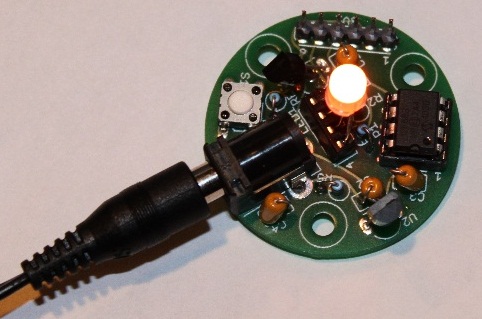
LED based projects require a lot of skill and hence only experienced circuit designers try out these circuits. But there are also a few circuits in this genre that can be done by amateur electronic hobbyists. The temperature candle is one such circuit. Read on to know more about this.

Temperature

The hardware components that are required to build this circuit are listed below:
- Microcontroller
- Temperature Sensor
- RGB LED
- PCB

The circuit design is pretty simple. The LED is made to flicker by the microcontroller and the color is based on the ambient temperature at that point. The temperature of the room can be known by observing the color of the LED.

The temperature value is obtained in degree Celsius. This value is received as a result of pressing the reset button on the PCB. This value can also be obtained by providing power to the device. Once the device is powered up, the change in temperature is indicated. The blue LED is triggered for a temperature increase of 10 degrees. The red LED is triggered for a temperature increase of a single degree.

Suppose, the ambient temperature is 23 degrees celsius, The circuit works in such a way that the blue LED is made to blink twice and the red LED is made to blink 3 times. Soon after this, an orange colored flicker is observed as the LED goes into canfle mode.

Since through hole components are used in this circuit, it is very cheap to construct and the components can be easily soldered. The circuit also contains a jack for connecting to a Microchip Pickit 3 programmer / debugger. This reduces the complexity involved in code modification and download.
Read more

Tuesday, October 28, 2014

Two Colour LED Lights Bar

This circuit is a circuit run on alternating two insignia.It uses the 2-color LED with a built-participating in 3-pin single.This preference look for away the glow of every LED until the base.It turns alternating to one more color.In in the least way to the moon on the moon essential end, afterward the LED end of the first LED.Circuit consists of, nand gate ic.Two 10 Counter circuits IC, and IC JK flip washout .Company of the circuit is not speaking into 3 sets.It is a solid of gesture generators, a set of parade and control.Set the signal generator is IC1a,and IC1b quantity 4011 is a signal generator.The R2, R3, C2 determine the frequency generated.The hint is fed to a set of impressions is the figure 4011 IC2 and IC3.The 10 counter circuits to output to the LED, and Is the same, but the effort should ensue performed individual by the side of region.

Two

Therefore, the show from pin 11 of IC 2 and tested pro D2 and D3,To pin 3 of IC4.The integrated circuit IC 4 is a JK flip slump is connected to a T flip flop.The signal input pin 3 and pin 1 is the output hint at.Which sends a signal to the Reset IC either obstruct working.IC4 on the anniversary, it want output the originally moment in time, happening contrast to pin1.IC3 progress to handiwork, IC2 stopped.
IC2 is controlled by signals from pin 1 of IC4, to IC1c.earlier to control IC2.The IC3 is connected to pins 1 through D1 to the control again
Read more

Wednesday, September 24, 2014

SP LED Scanner

Here may be a easy LED chaser simulating a scanner through the rear and forth light-weight result. It used high bright White LEDs to grant the chaser result. The circuit uses an oscillator to provide quick pulses and a decade counter to drive the LEDs.

IC1 is intended as an astable multivibrator to grant continuous positive pulses to the last decade counter. Variable resistor VR1, R1 and C1 kind the timing elements. By adjusting VR1, its attainable to alter the speed of the scanning LEDs.

Output pulses from IC1 are fed to the clock input of the last decade counter IC2. Resistor R2 keeps the clock input of IC2 low once every positive to negative transitions of input pulses. this can be necessary as a result of generally the clock input of the last decade counter stays positive and doesnt settle for input pulses.
LED Scanner Circuit

All the 10 outputs are utilized in the circuit to drive the LEDs. Diodes D1 through D10 (IN 4148) do the trick of forward and backward chasing result. Out of the 10 diodes, eight diodes kind OR gates to direct the outputs of IC2 to LEDs. The remaining 2 diodes maintain the brightness of the 2 ungated LEDs. 1st six outputs of IC2 works within the straight thanks to provide the running result.

The diode connected to the pin five of IC2 is connected to the cathode of the diode from pin ten (5th LED). This reverses the running sequence within the backward direction. Output half-dozen drives the fourth LED and also the method repeats up to the 2nd LED connected to output pin2.The reset pin fifteen and also the Clock inhibit pin thirteen of IC2 are connected to ground so IC2 will run freely.
Read more

Dimmer Brightness LED Driver Circuit Diagram

This is a very simple circuit of a dimmer, ie a controller LED brightness, which is powered from the USB port of a PC and a connection is very simple. The resistor R1 sets the maximum current of the LED with the maximum potentiometer, resistor R2 should have a resistance of 10x to 100x greater than R1. The table shows which components to use in accordance with the selected LED.


Dimmer-Brightness LED Driver Circuit Diagram

Dimmer-Brightness LED Driver Circuit Diagram

Read more

BRIGHT FLASH FROM FLAT BATTERY 3v WHITE LED FLASHER

BRIGHT FLASH FROM FLAT BATTERY
This circuit can flash a white LED, on a provide from 2v to 6v and turn out a really bright flash. The circuit takes regarding 2mA and recent cells are often used. the 2 100u electros in parallel produce a much better flash when the availability is 6v.


3v WHITE LED FLASHER
This will flash a white LED, on 3v provide and turn out a really bright flash. The circuit produces a voltage on top of 5v if the LED isnt in circuit however the LED limits the voltage to its characteristic voltage of three.2v to 3.6v.   The circuit takes regarding 2mA an is really a voltage-doubler (voltage incrementer) arrangement.
Note the 10k charges the 100u. It doesnt illuminate the LED because the 100u is charging and also the voltage across its invariably less than 3v. When the 2 transistors conduct, the collector of the BC557 rises to rail voltage and pulls the 100u HIGH. The negative of the 100u effectively sits just under the positive rail and also the positive of the electro is regarding 2v on top of this. All the energy within the electro is pumped into the LED to supply a really bright flash. 


Read more

Temperature Candle Using LED

LED based projects require a lot of skill and hence only experienced circuit designers try out these circuits. But there are also a few circuits in this genre that can be done by amateur electronic hobbyists. The temperature candle is one such circuit. Read on to know more about this.

Hacks and Mods: Temperature Candle Using LED

The hardware components that are required to build this circuit are listed below:
  • Microcontroller
  • Temperature Sensor
  • RGB LED
  • PCB

The circuit design is pretty simple. The LED is made to flicker by the microcontroller and the color is based on the ambient temperature at that point. The temperature of the room can be known by observing the color of the LED.

The temperature value is obtained in degree Celsius. This value is received as a result of pressing the reset button on the PCB. This value can also be obtained by providing power to the device. Once the device is powered up, the change in temperature is indicated. The blue LED is triggered for a temperature increase of 10 degrees. The red LED is triggered for a temperature increase of a single degree.
Suppose, the ambient temperature is 23 degrees celsius, The circuit works in such a way that the blue LED is made to blink twice and the red LED is made to blink 3 times. Soon after this, an orange colored flicker is observed as the LED goes into canfle mode.

Since through hole components are used in this circuit, it is very cheap to construct and the components can be easily soldered. The circuit also contains a jack for connecting to a Microchip Pickit 3 programmer / debugger. This reduces the complexity involved in code modification and download.
Read more

Tuesday, September 23, 2014

Build a 16 LED Chaser Circuit Diagram

This 16 LED Chaser Circuit Diagram is a double direction flash. Similar to Digital Ping- Pong 1, there is a movement of a lit dot, up and down along the LEDs length.

16 LED Chaser Circuit Diagram

16 LED Chaser Circuit Diagram


When the D16 lit the situation changes and there is a reverse movement. Lit D15-14 ……D16, is lit making circles when the circuit is under power. The IC1 is an unstable flip- flop supplying with stable frequency pulses (the frequency can be changed by TR1, adjusting the velocity of the LEDs up and down).

This frequency supplies the IC3 (which is a 4-Bit UP and DOWN counter) through 2 gates A-B of the IC2. The output counter supplies the IC4 that is the driver of the LEDs. The parts C- D of The IC2, make a R-S flip- flop, that changes situation, when the edge LEDs D1 and D16 lit.

We have an electronic limit for the situation change. In proportion the shape we make with the LEDs, we can have the proportionate optional result, making various effects.

Part List

R1= 100Kohms
R2= 220Kohms
R3= 470 ohms
TR1= 1Mohms
C1= 330nF 100V MKT
D1-16= LED 5mm
IC1= 555
IC2= 7400
IC3= 74193
IC4= 74154
Read more

Walking LED Circuit Diagram

 https://blogger.googleusercontent.com/img/b/R29vZ2xl/AVvXsEgvHSWw6zdmlFQwqbzKz0lAu3Ei0oMgN48-BNrCQfP3WgtozoJPqRKxvniCT-dZny1-5-SrcdQqVVVQAgSCFBWi8wV5s-S_IH5Lfddn9RJDr-XoF8QpAkzU_ubHiXrzD6ONVRvWv7K5aZ_x/s320/led indicatior dance.gif

Components list:

    R1_____________10K 1/4W Resistor
    R2,R3__________47K 1/4W Resistors
    R4______________1K 1/4W Resistor
    R5,R6,R7______100K 1/4W Resistors
    R8____________820R 1/4W Resistor
    C1,C3_________100nF 63V Ceramic or Polyester Capacitors
    C2_____________10΅F 50V Electrolytic Capacitor
    C4____________330nF 63V Polyester Capacitor (See Notes)
    C5____________100΅F 25V Electrolytic Capacitor
    D1___________1N4148 75V 150mA Diode
    D2-D11_________5 or 3mm. LEDs (any type and color)
    IC1___________LM358 Low Power Dual Op-amp
    IC2____________4017 Decade counter with 10 decoded outputs IC
    M1_____________Miniature electret microphone
    SW1____________SPST miniature Slider Switch
    B1_______________9V PP3 Battery
    Clip for PP3 Battery
    Additional circuit parts (see Notes):
    R9,R10_________10K 1/4W Resistors
    R11____________56R 1/4W Resistor
    D12,D13 etc.____5 or 3mm. LEDs (any type and color)
    Q1,Q2_________BC327 45V 800mA PNP Transistors
    Q3____________BC337 45V 800mA NPN Transistor 
Read more

Friday, September 19, 2014

Power on Reminder with LED Lamp Circuit Diagram

D. Mohan Kumar is famous name in the circuits world. There are ds Power-on Reminder with LED Lamp Circuit Diagram creation. Many a times equipment at workstations remain switched on unnoticed. In this situation, these may get damaged due to overheating. Here is an add-on device for the workbench power supply that reminds you of the power-on status of the connected devices every hour or so by sounding a buzzer for around 20 seconds. It also has a white LED that provides good enough light to locate objects when mains fails.

Power-on Reminder with LED Lamp Circuit Diagram

Power-on Reminder with LED Lamp Circuit Diagram
 
 Fig. 1 shows the circuit of power-on reminder with LED lamp. Here, IC NE555  (IC1) is wired as an astable multivibrator, whose time period is set to around six minutes using resistors R1 and R2, preset VR1 and capacitor C1 for sounding the buzzer every hour. The output of IC1 is fed to the clock input of IC CD4017 (IC2). Capacitor C3 and resistor R3 provide power-on-reset pulse to IC2.When power to the circuit is switched on, pin 3 of IC2 goes high. After around one hour, its output pin 11 (Q9) goes high and the buzzer sounds. This cycle repeats until the two npn transistors. The LDR offers a very high resistance in darkness, i.e., when no light falls on it. Therefore when power fails, transistor T1 gets reverse biased to drive transistor T2 and the white LED (LED2) glows. The lamp circuit is powered by a 9V rechargeable battery, which is charged via resistor R5 when mains is present. Thus in darkness, the LED remains power to the circuit is switched off.

Power-on Reminder with LED Lamp Circuit Diagram 1

 The automatic lamp is built around a light-dependent resistor (LDR) and ‘on.’Fig. 2 shows the power supply circuit. The AC mains is stepped down by transformer X1 to deliver a secondary output of 15V AC at 500 mA. The transformer output is rectified by a bridge rectifier comprising diodes D1 through D4, filtered by capacitor C5 and regulated by IC 7812 (IC3) to provide regulated 12V to the circuit. Capacitor C6 bypasses any ripple in the regulated output.

Sourced By: EFY Author D. Mohn Kumar
Read more

Build a Rechargeable Torch Based on White LED

Rechargeable torches don’t come without problems. You need to replace the bulbs and charge the batteries frequently. The average incandescent light-emitting diode (LED) based torch, for instance, consumes around 2 watts. Here’s a rechargeable white LED-based torch that consumes just 300 mW and has 60 per cent longer service life than an average incandescent torch.

 Rechargeable Torch Based on White LED Circuit Diagram


 Rechargeable Torch Based on White LED Circuit Diagram

Fig. 1 shows the circuit of the rechargeable white LED-based torch. The reactive impedance of capacitors C1 through C3 (rated for 250V AC) limits the current to the charger circuit. The resistor across the capacitors provides a discharge path for the capacitors after the battery is charged. The red LED1 indicates that the circuit is active for charging.

The torch uses three NiMH rechargeable button cells, each of 1.2V, 225 mAH. A normal recharge will take at least 12 hours. Each full recharge will give a continuous operational time of approximately 2.5 hours. Recharge the battery to full capacity immediately after use to ensure its reliability and durability. The charging current is around 25 mA.

Build a Rechargeable Torch Based on White LED

A voltage booster circuit is required for powering the white LEDs (LED2 through LED4). An inverter circuit is used to achieve voltage boosting. Winding details of the inverter transformer using an insulated ferrite toroidal core is given in the schematic. The number of 35 SWG wire turns in the primary and secondary coils (NP and NS) are 30 and 3, respectively. If the inverter does not oscillate, swap the polarity of either (but not both) the primary or the secondary winding. A reference voltage from resistor R5 provides a reflected biasing to the transistor, and keeps the output constant and regulated. The suggested enclosure for the torch is shown in Fig. 2.


Author: T.A . Babu
Read more