You can Make Relay Based Motorcycle Alarm Circuit Diagrams. You can use them to protect your motorcycle - but they have many more applications. If you use relays with 6-volt coils - theyll protect your "Classic Bike". Both alarms are very small. The completed boards occupy about half a cubic-inch - 8 cc. The standby current is zero - so they wont drain your battery.
Relay Based Motorcycle Alarm Circuit Diagram 1 uses a SPCO/SPDT relay - but you really only need to use a SPST relay. If you are going to use the veroboard layout provided - youll need to use the style of relay specified. But you can build the alarm using whatever style of relay you have available.
Relay Based Motorcycle Alarm Circuit Diagram 1
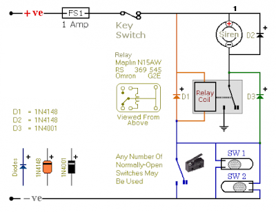
Any number of normally-open switches may be used. Fit the mercury switches so that they close when the steering is moved or when the bike is lifted off its side-stand or pushed forward off its centre-stand. Use micro-switches to protect removable panels and the lids of panniers etc. When one of the trigger-switches is closed - the relay will energize and the siren will sound.
You can choose what happens next. If you build the circuit as shown, the siren will continue to sound until you turn it off - or until the battery is exhausted. But, if you leave out D3 - the siren will stop sounding immediately the trigger-switch is re-opened.
While youre within earshot of your machine - the former configuration is best. You can always turn off the alarm yourself. But if you are going to be away from your bike for any length of time - and you dont want to cause a nuisance - then the latter configuration is probably more suitable. If you include a SPST switch in series with D3 - you can select the behaviour that best suits the circumstances at any given time.
Relay Based Motorcycle Alarm Circuit Diagram 1a

Relay coils and some sounders produce high reverse-voltage spikes that will destroy sensitive electronic components. D1 and D2 are there to short-circuit these spikes before they can do any damage. Although there is nothing in the alarm circuit itself that could be damaged - I have no idea what other electronic equipment might be connected to the same power supply. So I included the two diodes as a precaution. If youre satisfied that theres nothing on your bike that might be damaged in this way - you can leave out the two diodes.
Relay Based Motorcycle Alarm Circuit Diagram 2 uses a DPCO/DPDT relay - but you really only need to use a DPST relay. If you are going to use the veroboard layout provided - youll need to use the style of relay specified. But you can build the alarm using whatever style of relay you have available.
Relay Based Motorcycle Alarm Circuit Diagram 2

Any number of normally-open switches may be used. Fit the mercury switches so that they close when the steering is moved or when the bike is lifted off its side-stand or pushed forward off its centre-stand. Use micro-switches to protect removable panels and the lids of panniers etc. When one of the trigger-switches is closed - the relay will energize and the siren will sound.
You can choose what happens next. If you build the circuit as shown, the siren will continue to sound until you turn it off - or until the battery is exhausted. But, if you leave out the (yellow) solder-bridge in the top left-hand corner of the diagram - the siren will stop sounding immediately the trigger-switch is re-opened.
While youre within earshot of your machine - the former configuration is best. You can always turn off the alarm yourself. But if you are going to be away from your bike for any length of time - and you dont want to cause a nuisance - then the latter configuration is probably more suitable. Connect a SPST switch in place of the (yellow) solder-bridge - and you can select the behaviour that best suits the circumstances at any given time.
Relay Based Motorcycle Alarm Circuit Diagram 2 a

Relay coils and some sounders produce high reverse-voltage spikes that will destroy sensitive electronic components. D1 and D2 are there to short-circuit these spikes before they can do any damage. Although there is nothing in the alarm circuit itself that could be damaged - I have no idea what other electronic equipment might be connected to the same power supply. So I included the two diodes as a precaution. If youre satisfied that theres nothing on your bike that might be damaged in this way - you can leave out the two diodes.
Whichever alarm you build - the circuit board and switches must be protected from the elements. Dampness or condensation will cause damage. Without the terminal blocks - the board is small. Ideally, you should try to find a siren with enough spare space inside to accommodate it. Fit a 1-amp in-line fuse as close as possible to the power source. This is Very Important. The fuse is there to protect the wiring - not the circuit board. Instead of using a key-switch you can use a hidden switch; or you could use the normally-closed contacts of a small relay. Wire the relay coil so that its energized while the ignition is on. Then every time you turn the ignition off - the alarm will set itself.
When the alarms are not sounding - the circuits use no current. This should make them useful in other circumstances - where a power supply is not readily available. Powered by dry batteries - with the relay and siren voltages chosen to suit - the alarms could be fitted almost anywhere.
Sourced By : Streampowers


