Showing posts with label light. Show all posts

Saturday, October 18, 2014

For Bicycles Rear Light After Glow circuit and explanation

This article is of interest only to readers whose bicycle lights are powered by a dynamo. The laws on bicycle lights in the United Kingdom are stricter than in other countries and a dynamo is, therefore, a rarity in this country. From the point of view of traffic safety it is advisable (in UK obligatory) for cyclists to have the rear lamp of their bicycle to light even when they are at standstill. In principle, it is not very difficult to modify the existing rear light with afterglow: all this needs is a large enough energy reservoir. Since the after-glow is required for short periods of time only, a battery is not required: a large value capacitor, say, 1 F, is quite sufficient.

As the diagram shows, in the present circuit, the normal rear light bulb is replaced by two series-connected bright LEDs, D2 and D3. These are clearly visible with a current of only 6 mA (compared with 50 mA of the bulb). The current is set with series resistor R1. The LEDs are shunted by the 1 F capacitor, C1. Since the working voltage of this component is only 5.5 V, it is, in spite of its high value, physically small. An effective regulator is needed to limit the dynamo voltage adequately. Normal regulators cannot be used here, since they do not work at low voltages. Moreover, such a device would discharge the capacitor when the cycle is at standstill.

Rear
Rear Light After Glow Circuit Diagram

Fortunately, there is a low-drop type that meets the present requirements nicely: the Type LP2950CZ5.0. Of course, the dynamo output voltage needs to be rectified before it can be applied to the regulator. In the present circuit, this is effected by half-wave rectifier D1 and buffer capacitor C2. Diode D1 is a Schottky type to keep any losses low – important for this application, because the ground connection via the bicycle frame usually causes some losses as well. The value of buffer capacitor has been chosen well above requirements to ensure that C1 is charged during the negative half cycles of the dynamo voltage.
Read more

Thursday, October 16, 2014

Build a Simple Emergency Light and Alarm Circuit Diagram

This Simple Emergency Light and Alarm Circuit Diagram is permanently plugged into a mains socket andNI-CD batteries are trickle-charged. When a power outage occurs,the lamp automatically illuminates. Instead of illuminating alamp, an alarm sounder can be chosen.When power supply is restored, the lamp or the alarm isswitched-off. A switch provides a “latch-up” function, in orderto extend lamp or alarm operation even when power is restored.Circuit operation:Mains voltage is reduced to about 12V DC at C2`s terminals, bymeans of the reactance of C1 and the diode bridge (D1-D4). Thusavoids the use of a mains transformer.

 Simple Emergency Light and Alarm Circuit Diagram

Simple


Trickle-charging current for the battery B1 is provided by theseries resistor R3, D5 and the green LED D6 that also monitorsthe presence of mains supply and correct battery charging.Q2 & Q3 form a self-latching pair that start operatingwhen a power outage occurs. In this case, Q1 biasing becomespositive, so this transistor turns on the self latching pair.

If SW3 is set as shown in the circuit diagram, the lampilluminates via SW2, which is normally closed; if set the otherway, a square wave audio frequency generator formed by Q4, Q5 andrelated components is activated, driving the loudspeaker.If SW1 is left open, when mains supply is restored the lamp orthe alarm continue to operate. They can be disabled by openingthe main on-off switch SW2.If SW1 is closed, restoration of the mains supply terminateslamp or alarm operation, by applying a positive bias to the Baseof Q2.

Notes:

Close SW2 after the circuit is plugged.Warning! The circuit is connected to 220Vac mains, then some parts in the circuit board are subjected to lethal potential! avoid touching the circuit when plugged and enclose it in a plastic box. 

Parts List
R1____________220K 1/4W Resistor
R2____________470R 1/2W Resistor
R3____________390R 1/4W Resistor
R4______________1K5 1/4W Resistor
R5______________1R 1/4W Resistor
R6_____________10K 1/4W Resistor
R7____________330K 1/4W Resistor
R8____________470R 1/4W Resistor
R9____________100R 1/4W Resistor

C1____________330nF 400V Polyester Capacitor
C2_____________10΅F 63V Electrolytic Capacitor
C3____________100nF 63V Polyester Capacitor
C4_____________10nF 63V Polyester Capacitor

D1-D5________1N4007 1000V 1A Diodes
D6______________LED Green (any shape)
D7___________1N4148 75V 150mA Diode

Q1,Q3,Q4______BC547 45V 100mA NPN Transistors
Q2,Q5_________BC327 45V 800mA PNP Transistors

SW1,SW2________SPST Switches
SW3____________SPDT Switch

LP1____________2.2V or 2.5V 250-300mA Torch Lamp

SPKR___________8 Ohm Loudspeaker

B1_____________2.5V Battery (tw1o AA NI-CD rechargeable cells wired in series)

PL1____________Male Mains plug

Read more

Tuesday, September 23, 2014

Automatic Bathroom Light with Back up Lamp Circuit Diagram

Sometimes we forget to switch off the bathroom light and it remains on unnoticed for long periods. This circuit solves the problem of electricity wastage by switching off the lamp automatically after 30 minutes once it is switched on. The back-up LED lamp provided in the circuit turns on for three minutes when mains fails. This is helpful especially when you are taking a shower at night.

The circuit is built around binary counter CD4060 (IC2), which has a built-in oscillator and 14 cascaded bistable multivibrators. The oscillator generates clock pulses based on the values of resistors R3 and R4 and capacitor C3.

Automatic Bathroom Light with Back-up Lamp Circuit Diagram

Automatic Bathroom Light with Back-up Lamp Circuit Diagram
 

For the given values, Q11 output of IC2 goes high after 30 minutes of power-on. Resistor R2 resets the IC for proper operation. The output of IC2 is fed to the gate of the SCR via resistor R6 and LED2, which function as a voltage dropper as well as output status indicator.

When the SCR gets gate drive, it fires to energise relay RL1. The latching function of the SCR keeps the relay energised until the power to the circuit is switched off using switch S1. When the relay energises, its normally closed (N/C) contacts break and light turns off. LED1 indicates that the oscillator is working.

The back-up white-LED lamp comprising LED3 and LED4 gives ample light in the event of mains failure. It is powered by a 9V rechargeable battery, which is charged at around 200mA current via diode D6 and resistor R7 when the circuit is switched on.

The back-up lamp circuit is built around timer NE555 (IC3) designed as a monostable. The output of IC3 goes high for three minutes based on the values of preset VR1 and capacitor C9. When the circuit is switched on, IC3 gets power supply via diode D6 and its trigger pin 2 remains high due to resistor R8. As a result, its output remains low as long as mains is present.


When power fails, pin 2 of IC3 get striggered via capacitor C8 and the monostable output goes high to switch on the white LEDs (LED3 and LED4). Resistor R9 limits the current through the LEDs to a safe level. Diode D7 is forward biased to give full voltage to the monostable when power fails.

The power supply for the circuit is derived from a 15V AC, 250mA transformer. The secondary output is rectified by a full-wave rectifier comprising diodes D1 through D4. Capacitor C1 smoothes the resulting DC. Regulator IC 7812 (IC1) and capacitors C4 and C5 provide stabilised 12V for the circuit.

Assemble the circuit on a Vero board and enclose it in a watertight plastic case. Connect the bathroom lamp (either 25-watt bulb or 11-watt CFL tube) to the circuit via N/C contacts of the relay, so that it turns on when switch S1 is pressed. For easy access, fix switch S1 along with the neon indicator outside the bathroom.

Sourced By EFY Author D. Mohn Kumar
Read more

Simple Light Dimmer that Doubles as Voltmeter Circuit

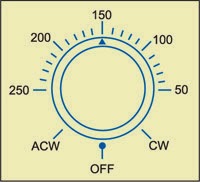
Measure AC mains voltage without using a multimeter. All you need to do is to slightly modify the light dimmer fitted at the base of a table lamp for use as a voltmeter. When the dimmer is turned anticlockwise to a point where the filament glow is just visible, that point can be used as the reference point for measuring the voltage.

Light dimmer Circuit Diagram

Light dimmer Circuit Diagram

First, remove the old knob and fix a circular white paper around the shaft. Now put back a skirted knob with a cursor as close to the paper as possible and mark two extremities of the pot on the paper as CW and ACW (see Fig. 2).

AC volts scale marking

AC volts scale marking


Switch on the lamp via a variac and feed 50 volts. Rotate the potmeter knob anticlockwise until the filament glow is just visible and mark that point against the cursor as 50V. Keep on increasing the voltage to 100, 150, 180, 200 and 220 using the variac and calibrating the scale for all the voltages. Now a voltage scale is created. The only snag is that the voltage is increasing in anti-clock-wise direction, which should not be a problem. The scale will not however be linear unlike the one shown in the sketch. Accuracy will depend on the calibration standard used and the tolerance is of the order of 1 percent ±5 volts. The diameter of the knob of potmeter and fineness of cursor can be of help in getting better accuracy and tolerance.

Pin configuration of BT134

Pin configuration of BT134


An ordinary fan regulator can be used with a lamp of 40, 60 or 100 watts and calibrated accordingly. The minimum measurable voltage is naturally limited to the one required for ‘just visible’ condition. With R1 open circuited the maximum scale voltage will be around 220 volts.


Author:  G.D. Sekhri Sourced : EFY
Read more

Build a Flashing Light with Twilight Switch Circuit Diagram

Build a Flashing Light with Twilight Switch Circuit Diagram. Flashing light is very useful in order to indicate any obstruction or working in progress. The project automatic flashing light with twilight switch flash light in dark but during day it automatically turns off itself.

The circuit diagram of automatic flashing light with twilight switch is shown below where LDR is used as sensor. In the presence of light LDR offer low resistance and in dark it offers high resistance. When there is absence light, LDR offer high resistances which turn off the transistor T1. Due to this darlington pair made from transistor T2 and T3 is turn on which further glow bulb. The feedback from its output is given to the junction of resistor R2 and LDR as shown in circuit diagram. Due to feedback this circuit works as oscillator which work as flasher. Variable resistor VR1 is used to adjust the sensitivity of LDR.

Flashing Light with Twilight Switch Circuit Diagram
 
Flashing Light with Twilight Switch Circuit Diagram


PARTS LIST
Resistors (all ¼-watt, ± 5% Carbon unless stated otherwise)
R1 = 2.2 KΩ
R2, R3 = 1 KΩ
R4 = 3.3 KΩ
VR1 = 25 KΩ
Capacitors
C1 = 1 µF – 10 µF
Semiconductors
T1, T2 = BC547B
T3 = BEL187-P
Miscellaneous
LDR
B1 = 3V to 10V bulb
Read more