Showing posts with label voltmeter. Show all posts

Wednesday, September 24, 2014

Ultra voltmeter and Voltage sensing Circuit Diagram

This is a circuit that detects tesões 1.8 V up to 230 Volts AC or DC. This circuit is not a novelty, but it proved so useful, simple and cheap that every technician should have one on the bench.

When the tip (red) positive is connected to a positive DC voltage and the black lead to the negative, the red LED lights up. Reversing the polarity green LED lights.

Connecting the probes to an AC source both LEDs will light. The lamp current is limited to 40mA @ 220V AC LED for illuminating and a filament starts from about 30V, shining more intensely with increasing tension.
Therefore, due to the behavior of the lamp filament, any voltage in the range from 1.8 to 230 V can be detected without changing component values​​.
 
Ultra voltmeter and Voltage sensing Circuit Diagram
 
Ultra voltmeter and Voltage sensing Circuit Diagram


List of Components

D1________5 or 3mm. red LED
D2________5 or 3mm. Green or yellow LED
LP1_______220V 6W lamp filament
P1________ Tip multimeter red
P2________ Probe Multimeter Black
Read more

Tuesday, September 23, 2014

Simple Light Dimmer that Doubles as Voltmeter Circuit

Measure AC mains voltage without using a multimeter. All you need to do is to slightly modify the light dimmer fitted at the base of a table lamp for use as a voltmeter. When the dimmer is turned anticlockwise to a point where the filament glow is just visible, that point can be used as the reference point for measuring the voltage.

Light dimmer Circuit Diagram

Light dimmer Circuit Diagram

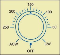
First, remove the old knob and fix a circular white paper around the shaft. Now put back a skirted knob with a cursor as close to the paper as possible and mark two extremities of the pot on the paper as CW and ACW (see Fig. 2).

AC volts scale marking

AC volts scale marking


Switch on the lamp via a variac and feed 50 volts. Rotate the potmeter knob anticlockwise until the filament glow is just visible and mark that point against the cursor as 50V. Keep on increasing the voltage to 100, 150, 180, 200 and 220 using the variac and calibrating the scale for all the voltages. Now a voltage scale is created. The only snag is that the voltage is increasing in anti-clock-wise direction, which should not be a problem. The scale will not however be linear unlike the one shown in the sketch. Accuracy will depend on the calibration standard used and the tolerance is of the order of 1 percent ±5 volts. The diameter of the knob of potmeter and fineness of cursor can be of help in getting better accuracy and tolerance.

Pin configuration of BT134

Pin configuration of BT134


An ordinary fan regulator can be used with a lamp of 40, 60 or 100 watts and calibrated accordingly. The minimum measurable voltage is naturally limited to the one required for ‘just visible’ condition. With R1 open circuited the maximum scale voltage will be around 220 volts.


Author:  G.D. Sekhri Sourced : EFY
Read more