Audio Power Amplifier is an important part in the reproduction of sound in a sound system. Audio Power Amplifier LM 3886 with power IC Audio Power Amplifier is a highly capable and able to produce 68 Watts with power rata2 4Ohm load and capable of producing power 38 Watt with 8Ohm load. With good sound reproduction capabilities of 20Hz-20kHz is also included on this LM3886 Audio Power Amplifier. LM3886 Audio Power Amplifier is equipped with spike protection that will protect the output circuit from overvoltage, undervoltage, overloads, konrsleting power supply, thermal runawaydan peak temperature. Audio Power Amplifier LM3886 also features a noise reduction system which can keep the audio from the noise well.
Image of Basic Audio Power Amplifier Series LM3886
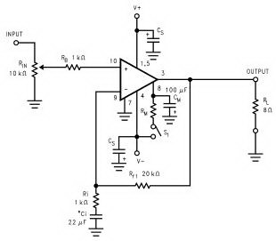
Audio Power Amplifier LM3886
Feature owned LM3886 Audio Power Amplifier
Read more
Image of Basic Audio Power Amplifier Series LM3886
Audio Power Amplifier LM3886
Feature owned LM3886 Audio Power Amplifier
- 68W cont. avg. output power into 4Ω at VCC = ± 28V
- 38W cont. avg. output power into 8Ω at VCC = ± 28V
- 50W cont. avg. output power into 8Ω at VCC = ± 35V
- 135W instantaneous peak output power capability
- Signal-to-Noise Ratio ≥ 92dB
- An input mute function
- Output protection from a short to ground or to the supplies via internal current limiting circuitry
- Output over-voltage protection against transients from inductive loads
- Supply under-voltage protection, not allowing internal biasing to occur Pls | VEE | + | VCC | ≤ 12V, Thus eliminating turn-on and turn-off transients
- 11-lead TO-220 package
- Wide supply range 20V - 94V
- Application of Audio Power Amplifier LM3886
- Stereo audio system
- Active Speaker
- High End Audio Power TV
- Suround Power Amplifier


 R1=15k


