Showing posts with label wire. Show all posts

Wednesday, September 24, 2014

Wire Break Alarm With Delay Circuits Diagram

Simple Wire-Break Alarm With Delay  Alarm and Security Here is a simple circuit of wire-break alarm that activates after a delay of 15 to 30 seconds. When the thin-wire loop running across the entrance door is broken, the alarm sounds after a delay of 15 to 30 seconds, the time period set through VR1. Thus the occupants get sufficient time to lock the room from the outside and catch the thief. 

 The circuit uses CD4060, which is a 14-stage ripple-carry binary counter/divider and oscillator. It is wired as a timer here and does not need input pulse for trigger. CD4060 gets activated as soon as the power supply is switched on. Output O13 of CD4060 goes high after the lapse of preset delay set through VR1. Transistor SL100 (T2) is wired as a switch to power the timer section built around CD4060. When the wire loop is closed, transistor T2 does not conduct. So power to the timer circuit is not available and the piezobuzzer does not sound. 

Wire-Break Alarm With Delay Circuit Schematic

Wire-Break Alarm With Delay Circuit Schematic

On the other hand, when the wire loop is broken by some intruder, transistor T2 conducts to power the circuit and the piezobuzzer sounds after 15 to 30 seconds. IC1 can be reset by connecting the wire loop or interrupting the supply. The circuit works off regulated 9V-12V. Assemble it on a general-purpose PCB and enclose in a metallic or plastic box of appropriate size. Connect piezobuzzer PZ1 through external wires and complete the installation. Link
Read more

Simple Wire Continuity Tester by LM709

While detecting discontinuities on a circuit board, it is probable to include resistors, semiconductors or other elements in measurements. This situation may cause wrong results. On the other hand sometimes the voltage or current of the multimeter may defect some circuit components.

Our circuit overcomes this inconvenient conditions. The circuit determines greater than 1 ohm values as discontinuity. Measure voltage is not more than 2mV. So no kind of diode, IC or other component is bypassed. Maximum current output of the circuit is about 200uA.

Simple Wire Continuity Tester by LM709 
Simple Wire Continuity Tester by LM709

Indicator of the circuit is a LED. Voltage supply may be two 9 Volt batteries. Voltage adjustment of the amplifier is done by P1 potentiometer. To do this process, first short circuit the probes and then turn P1 until LED brights. When you separate the probes again LED will fade out. This is a cheap and very useful circuit. You can build it on a PCB to use more easily.
Read more

Tuesday, September 23, 2014

Simple 220V Live Wire Scanner Circuit

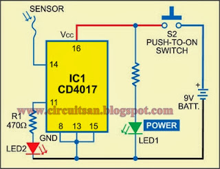
This simple circuit lets you scan a 220V live wire. The clock input of the IC is connected to a wire, which acts as the sensor. Here, we have used 10cm length of 22SWG wire as the sensor.

When you hold the sensor (metallic conductor or copper wire) close to the live wire, electric field from mains activates the circuit. As the input impedance of the CMOS IC is high, the electric field induced in the sensor is sufficient to clock it. The output obtained at pin 11 of CD4017 drives the LED. Flashing of the LED (LED2) indicates the presence of mains, while LED1 indicates that the scanner is active.

220V Live Wire Scanner Circuit Diagram

220V Live Wire Scanner Circuit


The circuit can be used to find stray leakage from electrical appliances like fans, mixers, refrigerators, etc. It can be easily assembled on any general-purpose board or the discrete components can be directly soldered on the IC.

A 9V PP3 battery powers the circuit. If you use a mains adaptor, make sure that it is well regulated and isolated; otherwise, even the stray electric field from mains transformer will clock the circuit.

Caution. Use insulated wire as sensor to avoid risk of exposure to live AC mains.


Author: T.A. Babu EFY
Read more