Showing posts with label 220v. Show all posts

Tuesday, September 23, 2014

Simple 220V Live Wire Scanner Circuit

This simple circuit lets you scan a 220V live wire. The clock input of the IC is connected to a wire, which acts as the sensor. Here, we have used 10cm length of 22SWG wire as the sensor.

When you hold the sensor (metallic conductor or copper wire) close to the live wire, electric field from mains activates the circuit. As the input impedance of the CMOS IC is high, the electric field induced in the sensor is sufficient to clock it. The output obtained at pin 11 of CD4017 drives the LED. Flashing of the LED (LED2) indicates the presence of mains, while LED1 indicates that the scanner is active.

220V Live Wire Scanner Circuit Diagram
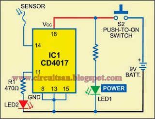
220V Live Wire Scanner Circuit


The circuit can be used to find stray leakage from electrical appliances like fans, mixers, refrigerators, etc. It can be easily assembled on any general-purpose board or the discrete components can be directly soldered on the IC.

A 9V PP3 battery powers the circuit. If you use a mains adaptor, make sure that it is well regulated and isolated; otherwise, even the stray electric field from mains transformer will clock the circuit.

Caution. Use insulated wire as sensor to avoid risk of exposure to live AC mains.


Author: T.A. Babu EFY
Read more

Simple 100W Inverter 12V to 220V Circuit Diagram

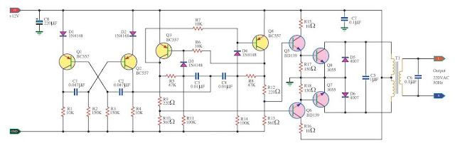
How to Build a100W Inverter 12V to 220V Circuit Diagram. When use the electric appliances that want 220V AC 50HZ, which have small-sized about 100Watt not exceed. By when you apply outside home, as a result have to have Mini power inverter about 100Watt, perform modify from work electricity forces of battery 12V give tall fair the work. 

100W Inverter 12V to 220V Circuit Diagram
 
100W Inverter 12V to 220V Circuit Diagram
 If you are New user electronics or want to economize or want to build electronics project use by oneself. I begs for to advise this circuit , because it uses , transistor number BC557 or the number replaces, perform oscillator generator. Then have power transistor 2N3055 numbers perform to drive coil transformer for converter voltage give tall go up 220V AC 50HZ at the electric power about 100 watt not exceed. When apply to transformer about 2A-3A. Picture circuit detail and like model PCB Board.

 PCB


Sourced By www.circuitsstream.blogspot.com
Read more

Friday, September 19, 2014

Simple 500W 12V to 220V Inverter

500W 12V to 220V Inverter Circuit Diagram

500W 12V to 220V Inverter Circuit Diagram
 
This is a 500W DC-to-AC inverter circuit diagram which produces an AC output at line frequency and voltage. 12VDC to 220V 50Hz inverter circuit will power 220V or 110V appliances from 12V car battery. The circuit is easy to make and is low cost. Use proper transformer. The output (in watts) is up to you by selecting different power rating transformer and power transistor rating. If you load electronic device which require 120V AC, then use transformer with 120V in output.
Read more

500W Mos Fet Power Inverter from 12V to 110V 220V

 500W Mos-Fet Power Inverter from 12V to 110V/220V

 500W Mos-Fet Power Inverter from 12V to 110V/220V

500W Mos-Fet Power Inverter from 12V to 110V/220V

This circuit will provide a very stable "Square Wave" Output Voltage. Frequency of operation is determined by a pot and is normally set to 60 Hz. Various "off the shelf" transformers can be used. Or Custom wind your own FOR BEST RESULTS. Additional MosFets can be paralleled for higher power. It is recommended to Have a "Fuse" in the Power Line and to always have a "Load connected", while power is being applied. The Fuse should be rated at 32 volts and should be approximately 10 Amps per 100 watts of output. The Power leads must be heavy enough wire to handle this High Current Draw!
Read more