Showing posts with label indicator. Show all posts

Wednesday, November 5, 2014

Automotive Voltage Indicator

Monitors battery voltage, Three-LED Display. Connecting this circuit to the battery of your vehicle, you will always know at a glance the approximate voltage available. An indication of battery voltage is useful to the motorist for monitoring the batterys capacity to deliver current, and as a check on the efficiency of the dynamo or alternator. Threshold voltages of the Leds are set by means of two Zener Diodes (D6 & D10) plus two further Diodes wired in series (D4, D5 and D8, D9 respectively) adding a step of about 1.3V to the nominal Zener voltage.

Automotive Voltage Indicator Circuit Diagram :

 indicator cicuit diagram
Parts:
R1 = 1k
R2 = 100K
R3 = 1k
R4 = 3.3K
R5 = 3.3K
R6 = 1k
R7 = 3.3K
R8 = 3.3K
Q1 = BC547
Q2 = BC547
Q3 = BC557
D1 = Red Led
D2 = Amber Led
D3 = 1N4148
D4 = 1N4148
D5 = 1N4148
D6 = BZX79C10
D7 = Green Led
D8 = 1N4148
D9 = 1N4148
D10 = BZX79C12

Notes:
  • Red LED D1 is on when battery voltage is 11.5V or less. This indicates a low battery charge.
  • Amber LED D2 is on when battery voltage is comprised in the 11.5 - 13.5V range. This indicates that the battery is good if the motor is off. When motor is running, this indicates no charge from dynamo or alternator.
  • Green LED D7 is on when battery voltage is 13.5V or more. This indicates a normal condition when motor is running and dynamo or alternator is charging.
Read more

Thursday, October 2, 2014

Mains Interruption Counter with Indicator Circuit Diagram

This circuit counts mains supply interruptions (up to 9) and shows the number on a 7-segment display. It is highly useful for automobile battery chargers. Based on the number of mains interruptions, the user can extend the charging time for lead-acid batteries.

Mains Interruption Counter Circuit Diagram

Mains Interruption Counter Circuit Diagram

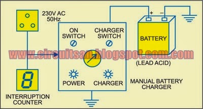
Fig. 1 shows the circuit of the interruption counter with indicator. A 9V (PP3 or 6F22) battery powers the entire circuit. Fig. 2 shows the block diagram of the mains interruption counter circuit along with the battery charger and lead-acid battery as used in automobile battery charger shops.When 9V is applied to the circuit, IC2 is reset by the power-on-reset signal provided by capacitor C3 and resistor R5 and the 7-segment display (DIS1) shows ‘0.’ The 230V AC mains is fed to mains-voltage detection optocoupler IC MCT2E (IC1) via capacitor C1 and resistors R1 and R2 followed by bridge rectifier BR1, smoothing capacitor C2 and current-limiting resistor R2. Illumination of the LED inside optocoupler IC1 activates its internal phototransistor and clock input pin 1 of IC2 is pulled down to low level.

Mains Interruption Counter Circuit Diagram  2


IC CD4033 (IC2) is a decade counter/7-segment decoder. Its pin 3 is held high so that the display initially shows ‘0.’ Clock pulses are applied to clock input pin 1 and clock-enable pin 2 is held low to enable the counter.Seven-segment, common-cathode display DIS1 (LTS543) indicates the mains interruption count. Capacitor C2 provides a small turn-on delay for the display.When mains fails for the first time, clock input pin 1 of IC2 again goes high and display DIS1 shows ‘1.’ When mains resumes, pin 1 of IC2 goes low and DIS1 continues to show ‘1.’ When mains fails for the second time, clock input pin 1 of IC2 goes high and display DIS1 shows ‘2.’ When mains resumes, pin 1 of IC2 again goes low and DIS1 continues to show ‘2.’ This way, the counter keeps incrementing by ‘1’ on every mains interruption. Note that this circuit can count up to nine mains interruptions only.

Sourced By: EFY Author:  T.K. Hareendran
Read more

Wednesday, September 24, 2014

Indicator Balance Stereo Sound Circuit Diagram

This is an Indicator Balance Stereo Sound Circuit Diagram, that is, it causes the two channels are to the same output level. This circuit eliminates the problems that may occur during recording and playback sound. It is connected to the output terminal of the speakers in the right channel and the left channel of the amplifier. To make the adjustment has to be zero in the middle of the window, however, if the signal level on the left channel is higher than that measured dO right channel will divert to the left (or right if the opposite occurs) .

Indicator Balance Stereo Sound Circuit Diagram
 

Indicator Balance Stereo Sound Circuit Diagram

Read more

Tuesday, September 23, 2014

Simple Brake Failure Indicator Circuit Diagram

This is a Simple Brake Failure Indicator Circuit Diagram that constantly monitors the condition of the brake and gives an audio-visual indication. When the brake is applied, the green LED blinks and the piezo buzzer beeps for around one second if the brake system is intact. If the brake fails, the red LED glows and the buzzer stops beeping.

The circuit will work only in vehicles with negative grounding. It also gives an indication of brake switch failure.

Simple Brake Failure Indicator Circuit Diagram

Simple Brake Failure Indicator Circuit Diagram


In hydraulic brake systems of vehicles, a brake switch is mounted on the brake cylinder to operate the rear brake lamps. The brake switch is fluid-operated and doesn’t function if the fluid pressure drops due to leakage. The fluid leakage cannot be detected easily unless there is a severe pressure drop in the brake pedal. This circuit senses the chance of a brake failure by monitoring the brake switch and reminds you of the condition of the brake every time the brake is applied.

The circuit uses an op-amp IC CA3140 (IC2) as voltage comparator and timer NE555 (IC3) in monostable configuration for alarm. Voltage comparator IC2 senses the voltage level across the brake switch. Its non-inverting input (pin 3) gets half the supply voltage through potential divider resistors R3 and R4 of 10 kilo-ohms each. The inverting input (pin 2) of IC2 is connected to the brake switch through diode D1, IC 7812 (IC1) and resistor R2. It receives a higher voltage when the brake is applied.

Normally, when the brake is not applied, the output of IC2 remains high and the red LED (LED1) glows. The output of IC2 is fed to trigger pin 2 of the monostable through coupling capacitor C2. Resistor R1 is used for the input stability of IC2. IC1 and C1 provide a ripple-free regulated supply to the inverting input of IC2.

IC3 is wired as a monostable to give pulse output of one second. Timing elements R7 and C4 make the output high for one second to activate the buzzer and LED2. Usually, the trigger pin of IC3 is high due to R6 and the buzzer and LED2 remain ‘off.’

When the brake pedal is pressed, pin 2 of IC2 gets a higher voltage from the brake switch and its output goes low to switch off the red LED. The low output of IC2 gives a short negative pulse to the monostable through C2 to trigger it. This activates the buzzer and LED2 to indicate that the brake system is working. When there is pressure drop in the brake system due to leakage, LED1 remains ‘on’ and the buzzer does not sound when the brake is applied.

The circuit can be assembled on any general-purpose PCB or perforated board. Connect point A to that terminal of the brake switch which goes to the brake lamps. The circuit can be powered from the vehicle’s battery.

The circuit requires well-regulated power supply to avoid unwanted triggering while the battery is charging from the dynamo. IC4, C6 and C7 provide regulated 12V to the circuit. The power supply should be taken from the ignition switch and the circuit ground should be clamped to the vehicle’s body. A bicolour LED can be used in place of LED1 and LED2 if desired.


Author: D. MOHAN KUMAR
Read more

Friday, September 19, 2014

Simple Multidoor Opening Alarm with Indicator

This door-opening alarm alerts you of intruders. You can use it for up to three doors. You simply need to fit a small unit including reed switch on each doorframe and fix a magnet on the moving door such that the magnet aligns with the reed switch when the door is closed. A separate unit incorporating the power supply, three LEDs and a buzzer is to be kept by your side inside your room. A three-core ribbon cable from this unit goes to each door unit. One core goes to the positive terminal, second to the negative terminal and third to the output of the unit. When the door is closed, the reed switch terminals are shorted and the alarm does not sound.

 Multidoor Opening Alarm with Indicator Circuit Diagram

 Multidoor Opening Alarm with Indicator Circuit Diagram

When door 1 is opened by someone, transistors in the corresponding door unit conduct and the buzzer sounds. LED1 glows to indicate opening of door 1. Due to diode latching action, the alarm will sound continuously even after the door is closed. It can be stopped only by pressing the reset switch of the door unit.

Regulated 9V to 12V DC for operating the circuit is derived from AC mains and fed to the three units mounted on the doors. Battery-backup is also provided. When all the three doors are simultaneously opened, all the three LEDs will glow.

This arrangement can be extended for more doors by increasing the number of door units connected to the audio-visual indication unit.


Author Pardeep G
Read more