Showing posts with label oscillator. Show all posts

Thursday, November 13, 2014

Transistor Schmitt Trigger Oscillator

The Schmitt Trigger oscillator below employs 3 transistors, 6 resistors and a capacitor to generate a square waveform. Pulse waveforms can be generated with an additional diode and resistor (R6). Q1 and Q2 are connected with a common emitter resistor (R1) so that the conduction of one transistor causes the other to turn off. Q3 is controlled by Q2 and provides the squarewave output from the collector.


In operation, the timing capacitor charges and discharges through the feedback resistor (Rf) toward the output voltage. When the capacitor voltage rises above the base voltage at Q2, Q1 begins to conduct, causing Q2 and Q3 to turn off, and the output voltage to fall to 0. This in turn produces a lower voltage at the base of Q2 and causes the capacitor to begin discharging toward 0. When the capacitor voltages falls below the base voltage at Q2, Q1 will turn off causing Q2 and Q3 to turn on and the output to rise to near the supply voltage and the capacitor to begin charging and repeating the cycle. The switching levels are established by R2,R4 and R5. When the output is high, the voltage at the base of Q2 is determined by R4 in parallel with R5 and the combination in series with R2. When the output is low, the base voltage is set by R4 in parallel with R2 and the combination in series with R5. This assumes R3 is a small value compared to R2. The switching levels will be about 1/3 and 2/3 of the supply voltage if the three resistors are equal (R2,R4,R5).

There are many different combinations of resistor values that can be used. R3 should low enough to pull the output signal down as far as needed when the circuit is connected to a load. So if the load draws 1mA and the low voltage needed is 0.5 volts, R3 would be 0.5/.001 = 500 ohms (510 standard). When the output is high, Q3 will supply current to the load and also current through R3. If 10 mA is needed for the load and the supply voltage is 12, the transistor current will be 24 mA for R3 plus 10 mA to the load = 34 mA total. Assuming a minimum transistor gain of 20, the collector current for Q2 and base current for Q3 will be 34/20 = 1.7 mA. If the switching levels are 1/3 and 2/3 of the supply (12 volts) then the high level emitter voltage for Q1 and Q2 will be about 7 volts, so the emitter resistor (R1) will be 7/0.0017 = 3.9K standard. A lower value (1 or 2K) would also work and provide a little more base drive to Q3 than needed. The remaining resistors R2, R4, R5 can be about 10 times the value of R1, or something around 39K.

The combination of the capacitor and the feedback resistor (Rf) determines the frequency. If the switching levels are 1/3 and 2/3 of the supply, the half cycle time interval will be about 0.693*Rf*C which is similar to the 555 timer formula. The unit I assembled uses a 56K and 0.1 uF cap for a positive time interval of about 3.5 mS. An additional 22K resistor and diode were used in parallel with the 56K to reduce the negative time interval to about 1 mS.

In the diagram, T1 represents the time at which the capacitor voltage has fallen to the lower trigger potential (4 volts at the base of Q2) and caused Q1 to switch off and Q2 and Q3 to switch on. T2 represents the next event when the capacitor voltage has risen to 8 volts causing Q2 an Q3 to turn off and Q1 to conduct. T3 represents the same condition as T1 where the cycle begins to repeat. Now, if you look close on a scope, you will notice the duty cycle is not exactly 50% This is due to the small base current of Q1 which is supplied by the capacitor. As the capacitor charges, the E/B of Q1 is reverse biased and the base does not draw any current from the capacitor so the charge time is slightly longer than the discharge. This problem can be compensated for with an additional diode and resistor as shown (R6) with the diode turned around the other way. 
Read more

Tuesday, November 4, 2014

Simple Oscillator Pipe Locator

Sometimes the need arises to construct a really simple oscillator. This could hardly be simpler than the circuit shown here, which uses just three components, and offers five separate octaves, beginning around Middle C (Stage 14). Octave # 5 is missing, due to the famous (or infamous) missing Stage 11 of the 4060B IC. We might call this a Colpitts ‘L’ oscillator, without the ‘C’. Due to the reactance of the 100-µH inductor and the propagation delay of the internal oscillator, oscillation is set up around 5 MHz. When this is divided down, Stage 14 approaches the frequency of Middle C (Middle C = 261.626 Hz). Stages 13, 12, 10, and 9 provide higher octaves, with Stages 8 to 4 being in the region of ultrasound.

Simple Oscillator/Pipe Locator Circuit Diagram


If the oscillator’s output is taken to the aerial of a Medium Wave Radio, L1 may serve as the search coil of a Pipe Locator, with a range of about 50 mm. This is tuned by finding a suitable hetero-dyne (beat note) on the medium wave band. In that case, piezo sounder Bz1 is omitted. The Simple Oscillator / Pipe Locator draws around 7 mA from a 9-12 V DC source.
Read more

Friday, October 3, 2014

ICL8038 Audio Oscillator Circuit

ICL8038 is a monolithic waveform generator IC that can aftermath sine, aboveboard and triangular waveforms with actual little distortion. The abundance can be programmed from 0.001Hz to 300 KHz application alien timing capacitor and resistor. Abundance accentuation and across-the-board can be accomplished by application an alien voltage. Other appearance of the ICL8038 are top linearity, top akin outputs, accompanying sine, square, triangle beachcomber outputs, low alien locations count, top temperature adherence etc.

The alive of ICL8038 is as follows. The external timing capacitor is answerable and absolved application two centralized accepted sources. The aboriginal accepted antecedent is on all the time and additional accepted is switched ON and OFF application a flip-flop. Suppose the additional accepted antecedent is OFF and the aboriginal accepted antecedent is ON, afresh the capacitor C2 will be answerable with a connected accepted (i) and the voltage beyond C2 increases linearly with time. When the voltage alcove 2/3 accumulation voltage, authoritative cast bomb is triggered and the aboriginal accepted antecedent is activated. This accepted antecedent carries bifold the accepted (2i) authoritative the capacitor C2 is absolved with a accepted i and the voltage beyond it drops linearly with time. When this voltage alcove 1/3 accumulation voltage, the cast bomb is resetted to the antecedent action and the aeon is afresh again.

The circuit diagram accustomed aloft shows a capricious audio abundance oscillator application ICL8038. Such a ambit is actual advantageous while testing audio accompanying projects. The abundance ambit of this ambit is 20Hz to 20KHz. POT R6 can be acclimated for adjusting the abundance while POT R9 can be acclimated for adjusting the distortion. POT R4 can be acclimated for adjusting the assignment aeon while POT R7 can be acclimated for adverse the variations in assignment cycle. C2 is the alien timing capacitor and R5 is a cull up resistor.

Read more

Wednesday, September 24, 2014

Oscillator Sine wave Circuit Diagram

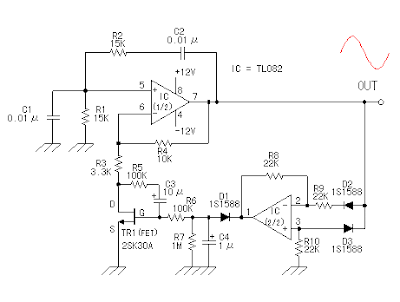
This circuit is a sine wave oscillator which uses operational amplifiers working in oscillation back (positive feedback), or the oscillation output to the input. This oscillator is called Wien bridge circuit is often used. The oscillator Sine wave oscillator is difficult to be done due to the distortion of the oscillation signal, different oscillator square wave, triangle wave oscillator (sawtooth).

Oscillator Sine wave Circuit Diagram

Oscillator Sine wave Circuit Diagram


In the case of C1 = C2 = C, R = R1 = R2, giving the frequency of oscillation and can be calculated using the following formula.

Formula Sine Wave Oscillator


The example of the circuit was made this time is shown below.
f = 1 / (2 x 3.14 x 10 -6 0.01 x 10 x 15 x 3)

f = 1 / (0.942 x 10 -3)
f = 1.062 x 10 3

f = 1062 Hz

The actual frequency of the circuit was 900 Hz.
Read more